Master Computer Networking
Complete guide to understanding networks, protocols, and data communication
Table of Contents
🧩 OSI Model
The OSI (Open Systems Interconnection) model is a conceptual framework that standardizes the functions of a telecommunication or networking system, dividing it into seven layers. This model helps in understanding how different network components interact to enable communication between devices, regardless of their underlying technology.
Key Concept: Created by ISO (International Organization for Standardization), think about layers like steps to communicate between devices. These steps happen in both devices - the sender and receiver do these steps in reverse. If the sender goes from 7 to 1, receiver goes from 1 to 7.
Data Transformation Process
At sender: At each layer, a header can be added to the data unit. At layer 2 a trailer is added as well. When formatted data unit passes through physical layer it is changed into an electromagnetic signal and transported along physical link.
Encapsulation: A packet (header and data) at level 5 is encapsulated in a packet in level 4, and so on. The data portion of packet at level N-1 carries the whole packet (data and header/trailer) from level N.
At destination: Data then moves back up through the layers. Headers and trailers attached to data at the corresponding layer are removed (decapsulated) and action appropriate to that layer are taken. At layer 5 the message is again in form appropriate to the application and is made available to user.
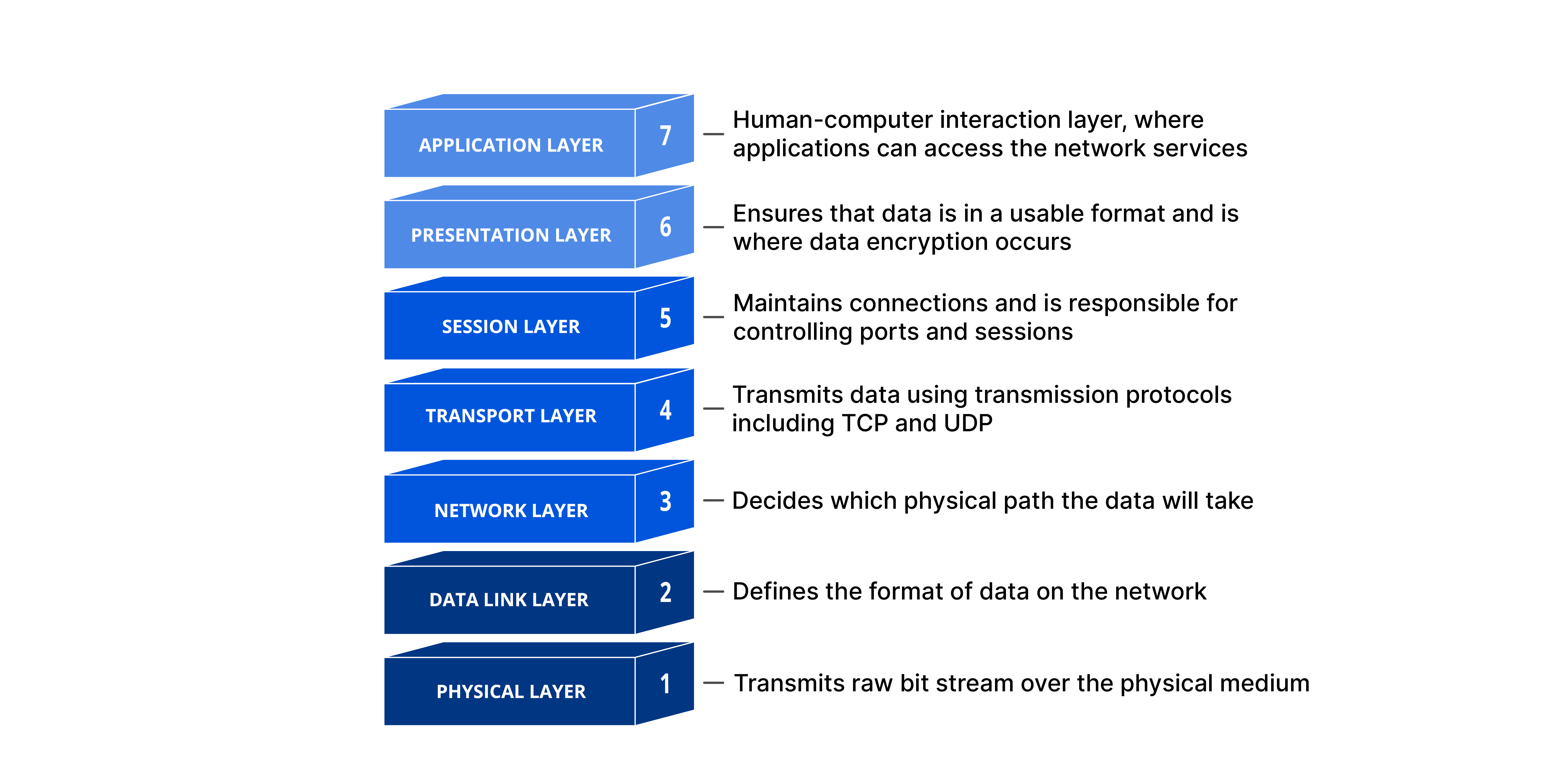
OSI Layers Breakdown
1. Physical Layer
The physical layer is responsible for movements of individual bits from one hop (node) to the next.
- Physical characteristics: Defines the interface between devices and media, including transmission media type
- Representation of bits: Defines how 0s and 1s are changed to signals
- Data rate: Defines number of bits sent per second and duration of bits
- Synchronization: Sender and receiver must use same bit rate and synchronized clocks
- Line configuration: Point-to-point or multipoint connections
- Physical topology: Star, mesh, bus, ring, or hybrid topology
- Transmission mode: Simplex, half-duplex, or full-duplex
2. Data Link Layer (Hop to Hop Delivery)
The data link layer is responsible for moving frames from one hop (node) to the next.
- Framing: Divides bit stream into data units called frames
- Physical addressing: Adds header with sender and receiver addresses
- Flow control: Prevents overwhelming the receiver
- Error control: Detects and retransmits damaged or lost frames
- Access control: Determines which device controls the link
MAC Address Example: Known as the MAC or link address, it's the address of a node as defined by its LAN or WAN. Ethernet uses 6-bytes (48-bits) physical address imprinted on the NIC.
3. Network Layer (End to End Delivery)
The network layer is responsible for the delivery of individual packets from source host to destination host across multiple networks.
- Logical addressing: Adds unique identifier (IP address) to packets
- Routing: Provides routing mechanism for routers to route packets to final destination
IP Addresses: IP addresses are necessary for universal communications independent of physical network. No two host addresses on the internet can have the same IP address. IP addresses are 32-bit addresses that uniquely define a host connected to the Internet.
Key Point: Physical addresses change from hop to hop, but logical addresses remain the same.
4. Transport Layer
Responsible for process-to-process delivery of the entire message.
5. Session Layer
The session layer is responsible for dialog control and synchronization.
- Dialog control: Allows communication in half or full duplex
- Synchronization: Adds checkpoints for recovery in case of failure
6. Presentation Layer
The presentation layer is responsible for translation, compression, and encryption.
- Translation: Converts between sender and receiver formats
- Encryption-Decryption: Ensures privacy and security
- Compression: Reduces number of bits for multimedia transmission
7. Application Layer
The application layer provides services to the user such as:
- Mail services
- File transfer and access
- Remote log-in
- Accessing the web (WWW)
- Telnet: Remote system login
- HTTP: Web file transfers
- SMTP: Electronic mail
🌐 TCP/IP Protocol Suite
The layers in the TCP/IP protocol suite do not exactly match those in the OSI model. However, when TCP/IP is compared to OSI, we can say that the TCP/IP protocol suite is made of five layers: physical, data link, network, transport, and application.
Physical Addressing in TCP/IP
Most local-area networks use a 48-bit (6-byte) physical address written as 12 hexadecimal digits; every byte (2 hexadecimal digits) is separated by a colon:
07:01:02:01:2C:4BA 6-byte (12 hexadecimal digits) physical address.
🏠 IP Addresses & Subnet Masks
Let us first look at the working definition of computer networks: Computer networks can be defined as the exchange of network packets between computing machines across the world with the help of data lines like wire cables, optical fibers, etc.
Commonly Used Terms in Computer Networks
Nodes
Nodes in computer networks mean any computing device such as computers, mobile phones, tablets, etc which try to send and receive network packets across the network to another similar device.
Network Packets
Network packets are nothing but the information or units of data that a source node wants to send/receive to/from the destination node.
Internet Protocol (IPs)
Consider you want to send a birthday gift to your friend on their birthday, where will you send it? To their street address right? Same is the case here. An IP of a computer device is the address of that device in a computer network.
Technical Definition: An IP address is a 32-bit number used which identifies devices in a network. All communication to and from the device in that network will be done in terms of its IP address.
IP Address Types
- IPv4: 32 bits (four bytes). Example: 104.244.42.129 (twitter.com's IPv4)
- IPv6: Eight hexadecimal numbers separated by ":". Example: 2001:0cb8:85a3:0000:0000:8a2e:0370:7334
IP Address Classes
IPv4 is classified into five classes named Class A, B, C, D, E.
Class A
First bit of first octet is constant and is "0"
- Default subnet mask: 255.0.0.0
- Network bits: 8, Host bits: 24
- Usable network bits: 7 (8-1 for class identification)
- Number of networks: 2^7 - 2 = 126
- Hosts per network: 2^24 - 2 = 16,777,214
- Range: 1.x.x.x to 126.x.x.x
Class B
First 2 bits are constant (10)
- Range: 128.0.x.x to 191.255.x.x
Class C
First 3 bits are constant (110)
- Range: 192.0.0.x to 223.255.255.x
Static vs Dynamic IP Addresses
- Static: IP addresses that remain constant for a device over time. Used for servers.
- Dynamic: IP addresses that change over time. Allocated by DHCP servers.
Important Note: A device can have multiple IP addresses at the same time. IP addresses are assigned to interfaces, not directly to computers.
Network Address Translation (NAT)
Network address translation is a technique used by routers to provide internet service to more devices with less usage of public IPs. A router is assigned a single IP address by the ISP and assigns private IPs to all connected devices.
NAT Example
If you're accessing medium.com (72.14.204.147) from your computer (192.168.1.100):
Private connection: 192.168.1.100:37641 → 72.14.204.147:80
Public connection: 104.244.42.129:59273 → 72.14.204.147:80
Dynamic Host Configuration Protocol (DHCP)
DHCP is responsible for assigning dynamic IP addresses to hosts. The DHCP server is maintained by the ISP or router and handles automatic IP allocation.
Domain Name System (DNS)
A Domain Name Server contains huge records of domain name to IP address mappings. When you type a URL, DNS servers translate the domain name to the corresponding IP address.
How DNS Works
- DNS is managed by your ISP
- When you type a URL, packets travel to your ISP's DNS server
- DNS server looks up the domain in its database
- If not found, it queries other DNS servers
- Returns the IP address or throws an error
Internet Service Providers (ISPs)
ISPs provide internet access and are organized in a hierarchical structure:
- Tier 1 ISPs: Major highways of the internet, connected to almost every network
- Tier 2 ISPs: Regional ISPs that provide services to organizations and consumers
- Tier 3 ISPs: Local ISPs that purchase bandwidth from Tier 2 ISPs
🔧 Network Devices
Network devices are physical devices that allow hardware on a computer network to communicate and interact with each other. They ensure efficient communication between connected devices by controlling data transfer, boosting signals, and linking different networks.
Functions of Network Devices
- Send and receive data between different devices
- Allow devices to connect